Boeing 737NG Collins Clone
737 autopilot control made & designed by wortelus
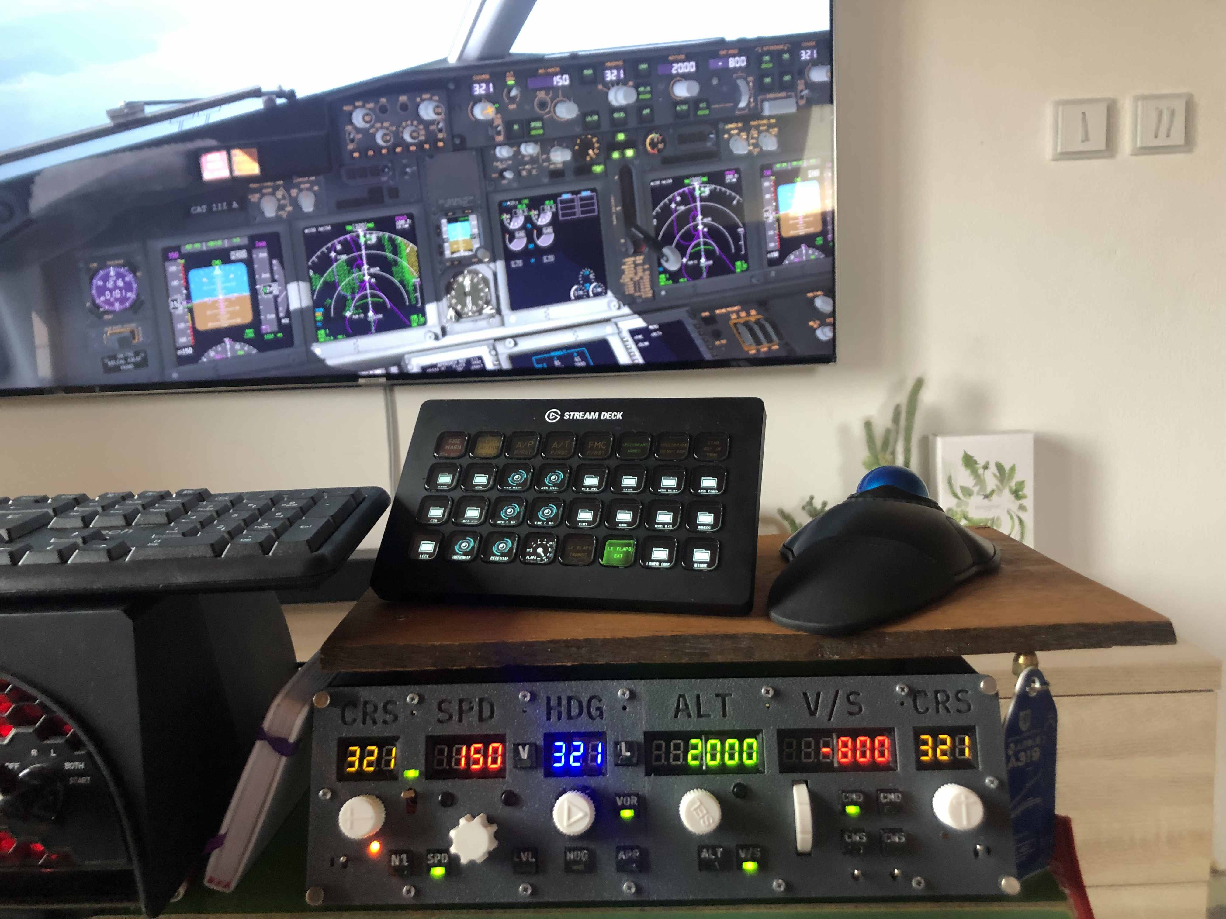
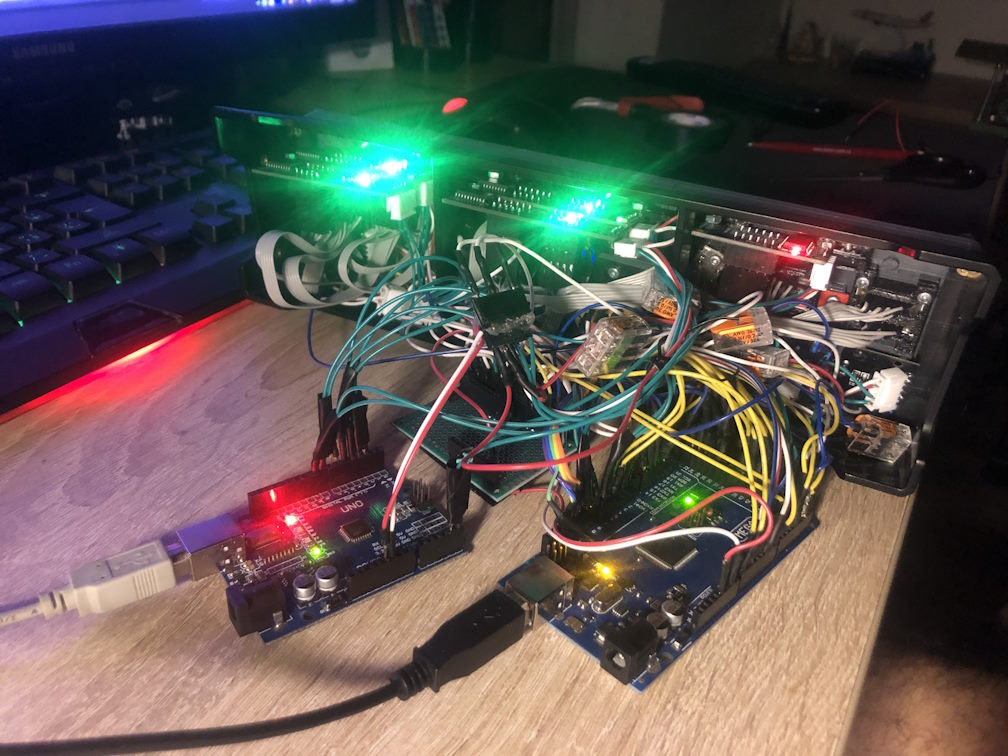
Working prototype, note the actual synchronization with the X-Plane state on the TV.
Intro
This project is a clone of an MCP panel from Boeing 737 Next Generation. Note that I don't mention replica, we should agree that this is far from the actual real life look. That is due to the fact that I wanted a small portable version to replace the Saitek Multi Panel, so I took its dimension and tried to scale down all of the controls, displays, philosophy and user experience the layout of the real thing provides. Also the one thing that makes this different than a replica is the visual absence of backlight source. Messing with laser engravers, CNC, spray painting etc. is for my project not a necessity as my simulator was never made to resemble the real thing as a replica.
After all, its just a more advanced toy...
Despite it, it features (I think) nearly every control from the original thing. Even the bank angle (which we'll show later) is modeled there, as this is not a complex, but an engineering problem (again, everything and every component is scaled down). Every part is made using a basic 3D printer - Ender 3 v2 with PETG filament.
Output Interfaces (displays, indicators)
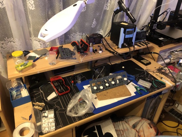
So let's start about the build log, the main thing was to get the components and try to fit them on the back plate. This is nothing hard, but what made it maybe lucky to fit is the fact that all of the 7-segment displays were able to fit next to each other on the backside. This is when the first challenge came up. That was the need to remove their TM1637 controling integrated circuits, which just couldn't fit next to each other on the back side of the panel. This made the necessity to actually mount the IC's on top of the back side (note in the picture). Not a complex problem but a lot of crimping, wiring and soldering to the mounted separate 7-segment displays.
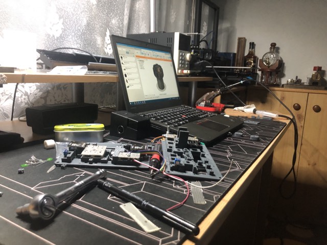
Also, the next challenge was the need to actually use different software to display them as the running software running all the other output and input peripherals), MobiFlight, is not supporting the TM1637 chips and is not even planning to do so. I ended up writing my own atmega328p software for a second arduino, which supplies the serial communication with the TM1637 chips. I might change to a different peripheral middleman plugin, but for now it is more than enough.
As per the output peripherals, this projects consists of those following components:
- 14 status mode indicators on buttons
- 3 signaling panel mounted LED's
- 5 controlling TM1637 chip boards
- 6 separate 7 segment displays
Input peripherals
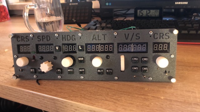
As far as I know, every peripheral that is on the real thing should be included. All 14 buttons, A/T switch, F/D switches, A/P disengage switches, rotary encoders for every mcp display. I did not even forget the most overlooked one, the bank angle selector. Most even hobby built real replicas lack this feature. It's installation is however different to other encoders, which can be mounted simply directly from the back, as you need two shafts - one to control the heading (the inner shaft), and the other one to actually control the bank angle (the outer shaft). The mechanism is partially displayed on the third picture.
The buttons were also tricky to build, as they were 10x10mm and had:
- Limited light indicator options
- Are too small to create some kind of easy installation mechanism
- Are too small to have the whole text on them
The LED indicators were solved by simple diffusion LEDs with dimensions of 2x5x7mm. They have proven to be a suitable choice and are closely fitted in their holes among with some hot glue directly on the buttons. This is probably the only installation limitation in terms of disassembly, as their removal requires some heating, which can damage the text and engravings if used irresponsibly (for too long or too hot).
Speaking of the engravings, this is quite an interesting part. The buttons needed to be printed with at least 0.3mm nozzle to achieve the detail in the small text. 0.3mm is quite enough as the Z-seams are doing more harm than the nozzle size at this point. The text is then needed to be painted to achieve the white-on-black look. The technique used to make this is the fun action here. We can fill the text using a VERY fine needle and a syringe. The paint used to do that is an idea I came across thanks to this YouTube video:
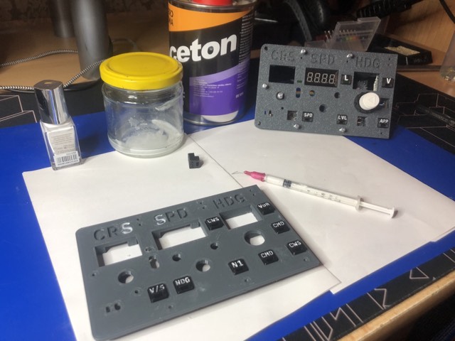
Nail polish diluted with the help of acetone has proven to be a very good technique if you practice a little bit with such small letters like the ones on the 10x10mm buttons.
However, I had to limit myself up to 3 letters to actually don't go under atom level scale.
Finally, the buttons are mounted on simple microswitches with elevated head. I'd like to
point out that you need to have kinda tuned out hole dimensions for them in the buttons to fit just right.
Gallery