The beginning of M-COMM
Posted on 16 November 2025 by wortelus — 4 min
Something new is slowly coming to life - another piece of avionics :)
While I procrastinate on my MTU Unit (more about that here), something else has struck my workbench -- a home-brewed copy of the Boeing 737 M-COMM radio.
It seems most natural to progress from the autopilot & throttles to a radio tuner. If you have ever flown the virtual skies along the voice of a real ATC, you know that controlling the voice communication is important. And not just that, it's a task that feels completely unnatural to do with a mouse/keyboard. Kills the immersion, yuck.
If you want to build a portable desktop cockpit setup like me, you will find the M-COMM panel just as beautiful as I do :). Not only do you control both the VHF/HF frequency bands, you also get to select the VHF channels 1-2-3. HF in case you like to fly over the ocean :) All under one tuning unit. This saves space and enables single-seated cockpits to manage all voice-related channels without the need for first officer's unit to be present.
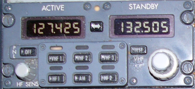
I hope mine will eventually get just as crusty as this real life version :) (image ref: http://www.b737.org.uk/communications.htm)
I'm completely revamping my electronics modus operandi, moving on from my 2023 MCP days. Today, if you want to build a piece of sim avionics, you want to:
- Have the boards made by professional services like JLCPCB or PCBWay, seriously, you don't want a wiring hell.
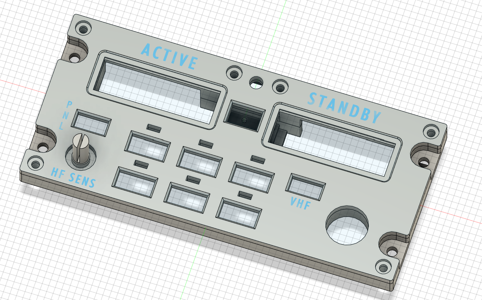
- Apply "cake layer" design philosophy, often using spacers, which usually consists of:
- Engraved front panel with backlight text
- Back panel as the foundation
- Cut acrylic sheet with LEDs for backlit front panel
- PCB(s) stacked on top of each other
I don't really care about the backlit part though. It's expensive and adds another layer of complexity. I don't really strive for the 100% real-life look, either. The end product should look smooth & professional, though :) no excuses there.
One good part is that these fabricators have a minimum order of 5-10 boards. This is actually a huge plus -- it means I'll have extras for spares. Or you can do one better - you can use one of the boards for panels of similar design -- the NAV panel (maybe even the ADF ?)
I'm learning my way around KiCad for the design work, and I have to say, the experience is great. The interface feels natural and simple, much like I did with Fusion360. This project has become so engaging that I'm finding it difficult to focus on my Diploma thesis :)
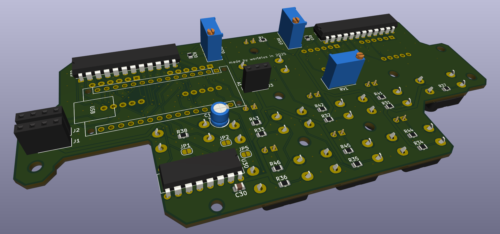
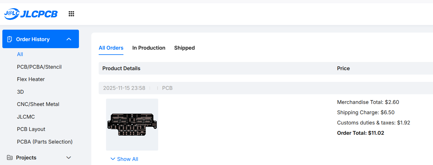
As you can see, I made the PCB to accommodate for the possible NAV / ADF panel. The J1-J5 jumpers can bypass the buttons to other, otherwise unused pins. Since the NAV / ADF panels have less IO, you don't need the 74HC165 input shift register anymore :). This cost-saving design choice saves you a chip and a few resistors on those 2 board variants. I will show you how it turns out after I order the SMD components (I chose 0805/2012), learn to solder with them and receive the boards, which I ordered for 11$ (with delivery costs & customs fees !).
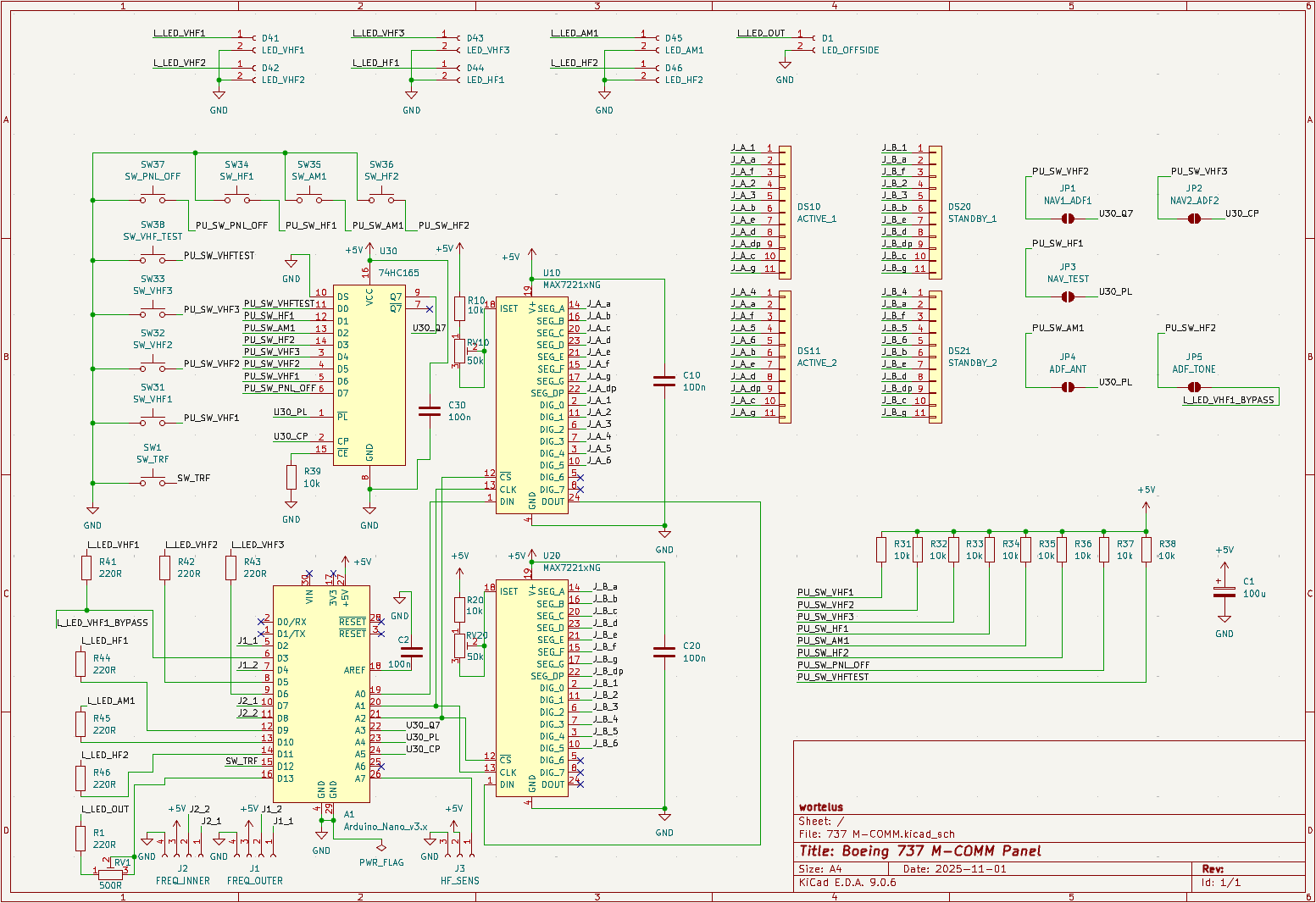
I designed the board to be modular & capable. The chips can be put into DIP sockets, the brightness of the 7-segments can be tuned via a trimmer (which also has 10k resistor in series, so you don't accidentally fry the chips / displays). The Arduino Nano fits into a female socket. The LEDs are on PWM capable pins, the 7th offside tuning light is on a trimmer again (no PWM). Every IC has its decoupling capacitor. Also, if you look closely, you will notice I used almost 100% of the IO pins Arduino Nano has to offer :). I am not an EE major, so I tried my best. The board is already ordered, so nothing I can change. Fingers crossed :)
The entire panel is designed to connect to the simulation via the excellent (free & open-source) MobiFlight software. That will ultimately be the heart of this whole project, beating along the 16MHz crystal on the heart of ATmega328P.
The black color looks slick :) really looking forward, stay tuned.
Signing out,
wortelus